Tutorial 09: Reading Analog Pins and Converting the Input to a Voltage
Arduino Course for Absolute Beginners
Reading Analog Pins and Converting the Input to a Voltage
In the last lesson you learned about using the analogRead() function to collect data from a sensor connected to one of the Arduino analog pins. The range of data we received from the analogRead() function was mapped between 0 to 1023.
What if we want to know the actual voltage being applied at the pin?
You Will Need
- Potentiometer (any resistance range will work)
- Jumper Wires – at least 3
- Persian Rug
Step-by-Step Instructions
- Place the potentiometer into your breadboard.
- Run a jumper wire from the 5-Volt pin of the Arduino to either one of the outside pins of the potentiometer.
- Run another jumper wire from one of the ground pins on the Arduino (labeled GND) to the other outside pin of the potentiometer.
- Run the final jumper wire from pin A0 on the Arduino to the middle pin of the potentiometer.
- Plug the Arduino into your computer.
- Open up the Arduino IDE.
- Open the sketch for this section.
- Click the Verify button on the top left side of the screen. It will turn orange and then back to blue once it has finished.
- Click the Upload button (next to the Verify button). It will turn orange and then back to blue once it has finished.
- On the menu bar, go to Tools > Serial Monitor – this will open the Serial Monitor window – you should see numbers rolling down this screen.
- Now adjust the knob of your potentiometer and watch the serial monitor window, the numbers should adjust between 0 and 5.

This image crafted with Fritzing.
The Arduino Code
/*
  ReadAnalogVoltage
  Reads an analog input on pin 0, converts it to voltage, and prints the result to the serial monitor.
  Graphical representation is available using serial plotter (Tools > Serial Plotter menu)
  Attach the center pin of a potentiometer to pin A0, and the outside pins to +5V and ground.

  This example code is in the public domain.
*/

// the setup routine runs once when you press reset:
void setup() {
  // initialize serial communication at 9600 bits per second:
  Serial.begin(9600);
}

// the loop routine runs over and over again forever:
void loop() {
  // read the input on analog pin 0:
  int sensorValue = analogRead(A0);
  // Convert the analog reading (which goes from 0 - 1023) to a voltage (0 - 5V):
  float voltage = sensorValue * (5.0 / 1023.0);
  // print out the value you read:
  Serial.println(voltage);
}
Discuss the Sketch
This sketch does the exact same thing as the last lesson sketch except for one important change. It takes the reading provided by the analogRead() function and converts it into the actual voltage value at the respective analog pin. Let’s start from the top to review what is taking place.
We have no variables to declare and initialize at the beginning of the sketch so we jump right into the setup() function. Inside the curly braces of setup() we begin serial communications by setting the baud rate. This is done using the function
Serial.begin(9600).
void setup() {

 // initialize serial communication at 9600 bits per second:

 Serial.begin(9600);

}
That is all there is to the setup() of this sketch. The next block of code is loop(). Inside the curly braces of loop() the first thing we do is read the value at analog pin A0 and assign it to an integer variable called sensorValue.
int sensorValue = analogRead(A0);
Once we have recorded this value, we want to convert it to an actual voltage. You will recall that the range returned by the analogRead() function is between 0 and 1023. We want this to reflect the actual voltage at the pin – which is between 0 and 5 volts depending on where the potentiometer knob is turned. So let’s take a look at how we might accomplish this…
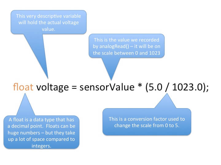
float voltage = sensorValue * (5.0 / 1023.0);
The first thing we encounter is a new data type – called float. A float is simply a number with a decimal point; say for example 3.14 or 2.17781778. Floats, also called floating point numbers, can be huge in value, and take much more time for the Arduino to churn through than integers – this is why they are used only when necessary.
We want the voltage variable set as a float data type because it will provide more resolution than an integer.
The voltage variable is set equal to a somewhat confusing calculation. Our goal is to take the value that analogRead() returns and convert it into an actual voltage value. We use a conversion factor to accomplish this feat. By multiplying sensorValue by (5.0/1023.0), it scales down the range from 0-1023 (which is the range that analogRead() returns) to the range 0-5 which is the actual range of the voltage. You can think of the conversion calculation by saying “sensorValue is to X volts as 5 volts is to 1023”, where X is the converted voltage value we are trying to determine.
Once we have this new value, it is assigned to the variable voltage – all of this on one line of code.
Let’s recap the program…
- Read the sensor value at an analog pin.
- Assign this value to a variable.
- Convert this value to a voltage
- Save the voltage measurement to another variable
- And then…
Well, we print it back to the serial monitor window so we can see what the voltage is at our pin.
The loop() will start over again, it will sample a new value at the pin, it will convert that value and print it, and loop and loop and loop – you get the idea.
Try On Your Own
- Switch from using the 5-volt pin on the Arduino to the 3.3-volt pin. Make sure to adjust the conversion factor.
- Instead of converting to a voltage value, can you change the conversion factor to return a range from 0 to 100?


[…] https://www.programmingelectronics.com/tutorial-05-reading-analog-pins-and-converting-the-input-to-a-v… […]
Let’s say we change the potentiometer for an MPU-6050. In the serial window, I would get the three axis outputs from the device. Can I use analogRead(A0) to save the output values? The analogRead seems is for a single variable. Not sure what is the format of the MPU6050 output, seems would be a 1×3 double array so how do you parse that out into the three separate variables to use for mapping and additional processing….
Great question Rick! I believe that gyro/accelerometer the MPU-6050 communicates through the I2C pins on the Arduino (not through the analog to digital convertor as demonstrated here).
I am pretty sure there is a library for reading from it. Here is a short article on using it from the Arduino website: http://playground.arduino.cc/Main/MPU-6050
Thanks. Will check it out.
When I attempt the first Try On Your Own challenge, the Serial Monitor returns values from 0.00 to 2.15. I have moved the jumper at A0 from the 5V pin to the 3.3V pin and changed the float statement to”float voltage = sensorValue * (3.3 / 1023.0);”. I have read the actual voltage at the 3.3V pin with a digital voltmeter and it is at 3.28 volts. What am I doing wrong?
The range between 0-1023 is 1024 values wide. So the factor should be (5.0/1024.0), right?